The balancing valve itself is a critical component in hydronic systems used to control and balance the flow of water across different parts of the system. It’s designed to ensure that the correct flow rate is delivered to various sections of the system to maintain optimal performance, energy efficiency, and comfort. The components of a balancing valve typically include:
1. Valve Body
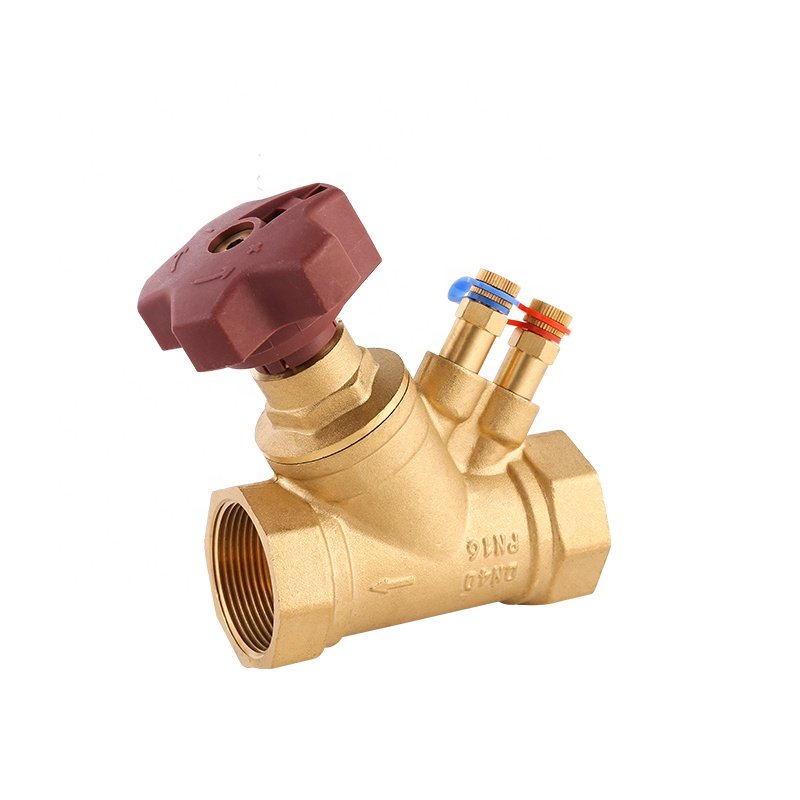
- Function: The main housing or casing of the valve that contains all the internal components. The valve body is usually made of brass, stainless steel, or other durable materials designed to handle water flow and pressure.
2. Flow Adjustment Mechanism
- Function: This is the part that allows you to control or adjust the flow rate through the valve. It is often a screw, knob, or dial that can be turned to change the opening of the valve. This mechanism is what allows the technician to fine-tune the system to the desired flow rate.
- Manual or Automatic: In manual systems, the adjustment is done by hand, whereas in automatic balancing valves, this is often controlled electronically or pneumatically based on real-time system conditions.
3. Flow Indicator
- Function: An indicator (like a graduated scale or dial) that provides a visual reference of the flow setting. This helps ensure that the desired flow rate is accurately set.
- Location: It’s usually integrated into the valve assembly or attached directly to the adjustment mechanism.
4. Pressure-Temperature Ports (P/T Ports)
- Function: These are small ports or fittings where pressure and temperature sensors can be attached to monitor the conditions inside the system. They help with balancing by providing information about the system’s pressure and temperature drop across the valve.
- Importance: Accurate readings from these ports are essential for calculating the proper flow settings, especially in complex systems with varying pressure conditions.
5. Seat and Plug (or Disc)
- Function: The seat and plug form the sealing mechanism inside the valve. The plug (or disc) controls the opening in the valve, regulating the flow. When the plug is moved, it changes the amount of space through which the water can pass, thereby adjusting the flow.
- Materials: These components are often made from durable, corrosion-resistant materials like rubber, Teflon, or metal alloys to ensure longevity and prevent leaks.
6. Spring (in some designs)
- Function: In some balancing valves, a spring is used to apply pressure on the valve plug or seat to maintain a constant pressure differential. This helps maintain consistent flow even as system pressures fluctuate.
- Purpose: Springs are typically used in pressure-independent balancing valves (PIBs), where they maintain a steady flow rate despite changes in system pressure.
7. Screw or Adjustment Mechanism (for flow regulation)
- Function: The screw mechanism is typically used in manual balancing valves to adjust the flow. Turning the screw raises or lowers the valve plug to regulate the flow through the valve.
8. Valve Stem
- Function: The stem connects the valve body to the flow adjustment mechanism and helps transmit the adjustment movement to the internal plug or seat. It allows for precise movement of the flow control element when the valve is adjusted.
9. Locking Mechanism
- Function: Some balancing valves come with a locking mechanism to ensure that once the desired flow rate is set, it cannot be accidentally changed. The lock may be mechanical (e.g., a nut or clip) or integrated into the adjustment mechanism itself.
- Purpose: This feature is particularly useful in maintaining the system balance during maintenance or operational changes.
10. Bypass (optional in some designs)
- Function: A bypass feature in some balancing valves allows water to flow around the valve when necessary, especially if the valve is closed or if balancing is not required in certain scenarios.
- Purpose: It can provide redundancy or prevent unnecessary pressure buildup in the system.
11. Gasket or Seals
- Function: Seals and gaskets are used to prevent leaks between the valve body and the various internal components, such as the valve plug or flow adjustment mechanism. They ensure that water flows only through the intended path and doesn’t escape through joints or threads.

Summary of Balancing Valve Components:
- Valve body: The casing that houses internal components.
- Flow adjustment mechanism: Controls how much water flows through the valve.
- Flow indicator: Visual aid to help set the flow rate.
- Pressure-temperature ports (P/T): For monitoring system pressure and temperature.
- Seat and plug: Regulate the flow of water.
- Spring: Used in pressure-independent valves for constant flow.
- Screw or adjustment mechanism: For fine-tuning the flow rate.
- Valve stem: Connects the adjustment mechanism to the plug.
- Locking mechanism: Ensures the flow setting stays constant.
- Bypass: Allows water to bypass the valve if necessary.
- Gasket or seals: Prevent leaks between components.
Would you like to dive into a specific type of balancing valve, such as pressure-independent or manual balancing valves? Or perhaps you’re interested in the installation or troubleshooting of these valves?
Choose IVALVECRAFT, choose reliable partner, enjoy the high quality and best service.